Showing posts with label lnb. Show all posts

Apr 22, 2019

C-Band LNB's: ZINWELL D21A Dual Pol LNBF Review

Today I will be reviewing a popular C-Band LNB: the Zinwell D21A Dual Porarity LNBF.

In large parts of the World satellite TV is delivered mainly using C-Band, instead of the Ku-Band. C-Band is still very popular in Asia, South America and Africa and requires the use of large antennas, usually bigger than 1 meter (3 feet) minimum. 

A C-Band LNB or LNBF works much the same way as a Ku-Band LNB. However, a C-Band LNB is much bigger (about 3x the size) than an equivalent Ku-Band LNB. This is because C-Band uses a much lower frequency range: 3700-4200Mhz for standard C-Band or 3400-4200Mhz for the extended C-Band. Another difference is that, since the C-Band frequency range is much narrower than the Ku-Band, C-Band LNB's only use one local oscillator instead of two.
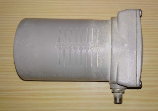
Zinwell D21A LNBF sideview
Zinwell D21A LNBF sideview. Note the F/D markings.

The sticker on the back reveals the main specs: 3.4-4.2 Ghz (extended C-Band), 15ºK noise and 67 dB gain.

Zinwell D21A C-Band LNBF specs
Zinwell D21A C-Band LNBF: 15ºK Noise, 67dB gain.

Like most C-Band LNBF, the Zinwell D21A is sold with a prime focus scalar ring and a depolarizer plate for circular polarity signals. 

C-Band scalar ring feed and depolarizer plate slab
Most C-Band LNBF's come with Prime-focus scalar ring and depolarizer plate.

The LNB waveguide (body) as markings and slides along the scalar ring to adjust for different dish F/D ratios.

C-Band LNBF scalar ring feed
Zinwell D21A with attached prime-focus scalar ring.

If the LNB is to be installed in an offset dish, a conical scalar feed horn should be used instead for adequate dish illumination.

C-Band LNBF conical scalar feed horn
With offset dishes a conical feed should be used for best performance.

The Zinwell D21A can receive linear (Vertical/Horizontal) polarity or circular polarity (Left Hand/Right Hand) signals. To receive circular polarity signals a depolarizer is inserted on the waveguide in front of the receiving probes. The depolarizer is made of Teflon or fibreglass and it is usually provided when you buy the LNB.

C-Band LNBF linear polarity vs circular polarity depolarizer
To receive circular polarity signals a depolarizer plate is inserted in the waveguide.

Opening the Zinwell D21A reveals the electronics. The local oscillator is under the metal casing and the adjustment screw indicates it is of the traditional DRO type. Some more recent mass market C-Band LNB designs using a PLL type oscillator are becoming commonly available. To learn about DRO and PLL oscillators please read this article. First stage amplification is done by NE3210S1 (K marking) super low noise HJ FET transistors. 

Zinwell D21A C-Band LNBF PCB board
Zinwell D21A LNB pcb
Performance
The Zinwell D21A Dual Polarity LNBF is a good performer. Very weak low symbol rate signals can take some time to lock, but this is normal. This LNB is marked as having 15ºK noise temperature, but it probably has around 20ºK true noise. There are C-Band LNB's marked as having noise temperatures as low as 12ºK, but this unlikely to be true and just marketing tricks.


May 3, 2018

Televés Universal Single LNB ref. 7475 & 147160 Review

Today I will be reviewing two single output Universal Lnb's from Televés, the Televés UNI LNB Ref. 7475 and the Televés UNI LNB Ref. 147160. These are Universal LNB's that cover the 10.7-11.7Ghz and 11.7-12.75Ghz Ku bands. They are LNBF's to be used with offset satellite dishes.

Televés is a well known and well regarded manufacturer of receiving and test equipment from Spain. They are probably more known worldwide for their triple boom UHF DAT antennas. Although Televés manufactures many of their products themselves, I believe these LNB's are sourced from the Far East.

This is the LNB (or LNBF) ref. 7475 model in typical Televés orange color.
 
Televes Universal LNB ref 7475
Televés ref. 7475 Universal Single Output LNB.

Televes Universal LNB ref 7475

And here is the Televés ref. 147160 LNB.

Televes Universal LNB ref 147160
Televés ref. 147160 Universal Single Output LNB.

The Televés universal single output LNB ref. 147160 is the same as the ref. 7475 LNB. The only difference is the color (white instead of orange). The label on the 147160 model states the LNB has a consumption of 200mA, but this is wrong! Consumption is 90mA maximum for both models. Both models have a 40mm neck and allow for some adjustment of the focus point on the dish. They come with multilingual installation instructions and spec sheet.

Televes Universal LNB ref 7475 teardown

The LNB casing is held with hex screws and is sealed with silicon. Here we can see the usual two local oscillator frequency adjustment screws.

Televes Universal LNB ref 7475 teardown

Bellow is a tear-down photo showing the internals of the Televés ref. 7475 LNB. Like most low price LNB's, the first stage amplification uses the common NEC NE3503M04 HJ-FET transistor, identified by the V75 marking. This transistor has an typical NF of 0.45dB @ 12 Ghz. Televés claims an NF (Noise Figure) of 0.5dB for this lnb. 

This is a DRO type lnb, the oscillators use ceramic dielectric elements which are hidden under the pcb. Televés claims a local oscillator stability of +/-2Mhz. This good enough in most cases, but many newer LNB designs use PLL technology instead, which offer improved stability. You can read about PLL and DRO oscillator technologies in my PLL vs DRO LNB article.

Televés claims a maximum phase noise of -75 dBc/Hz @10Khz. This is not a "stellar" value as many LNB's claim -80 dBc/Hz @10Khz. But we know anyone can claim whatever they want and the reality is quite different!

Televés states a typical gain of only 51dB. This is a lower than usual gain. Most lnb's have a minimum gain of 55 dB or more. Probably the gain figure is also wrong. Note: Televés now sell the 7475 LNB with a stated gain of 58 dB.

Voltage regulation, bias, polarization and band switching is done by the big SSOP-20 package UTC L8211L IC.

Build quality is good, but not perfect. In both lnb's solder flux residue can bee seen in the antenna probes solder joints. Although this is unlikely to have a significant impact on performance, no solder flux should remain in the pcb. 

Televes Universal LNB ref 7475 teardown inside pcb
Televés ref. 7475 Universal Single LNB.

And this image shows the internals of the Televés ref. 147160 LNB.

Televes Universal LNB ref 147160 teardown inside pcb
Televés ref. 147160 Universal Single LNB.

As we can see, the Televés ref. 147160 is exactly the same LNB as the Televés ref. 7475.

Tests
The despite the modest specifications, the Televés ref. 7475 and Televés ref. 147160 perform well, not favouring a particular part of the 10.7 to 12.75Ghz Ku band. Despite using traditional DRO technology this LNB has good frequency stability and is adequate for all but the very low symbol rate broadcasts.

Gain is similar to other tested Universal Lnb's, so probably around 57-58 dB, not the claimed low 51 dB.

Televés claim an NF of only 0.5 dB, while most brands claim 0.3 NF, 0.2 NF or even 0.1 NF. As I have written before, it is simply is not possible to reach such low NF values under normal working conditions. The best available transistors have 0.3 dB NF, at best! So, even 0.3 dB NF claims are unreal, and the Televés 0.5 NF claim is much closer to the real NF.

Televés say low NF is not the only important spec in an good LNB, but also how well it copes with a wide range of signal strengths from the satellite and that the Ref. 7475 copes well in such situations. Since reception conditions for a particular satellite vary from country to country (or even inside the same country) and with different size dishes, it is not easy to verify this claim. However, I agree with the statement from Televés stating that low NF is not the only important spec in an good LNB, but also how well it copes with a wide range of signal strengths.

Note: Televés now sells the ref. 7475 LNB with a claimed NF of 0.3 dB.

Download Televés ref. 7475 LNB specifications here (current version).
Download the NEC NE3503M04 N-Channel HJ-FET transistor datasheet here.

Apr 13, 2017

PLL vs DRO LNB - Which is better?

LNB's, every satellite TV system uses them. Universal, Ku band, C band, Ka band, single output, dual output, four outputs or even eight outputs, there are lnb's for every need. But essentially, little has changed in lnb technology for almost twenty years. 

PLL Ku band LNBF
One new development has materialized however, the massification of PLL (Phase Locked Loop) oscillator technology. Before we go further let me quickly explain about this oscillator stuff.

LNB's are electronic devices whose purpose is to amplify and convert the extremely weak and extremely high frequency satellite signals into stronger and lower frequency signals capable of being carried over a coaxial cable to the satellite receiver inside your home. To convert a frequency to another frequency an oscillator circuit is required.

Most lnb's use what is called DRO (Dielectric Resonator Oscillator) oscillator technology. And PLL oscillators in lnb's are nothing new, but until about five years ago use of PLL controlled oscillators was restricted to professional use (and expensive) LNB's. This has changed, and now PLL technology can be found on many low cost mass market lnb's. But is it worthwhile? Let's compare both technologies.

DRO technology lnb
Conventional LNB's use dielectric resonator oscillators (DRO) to generate the local oscillator frequencies necessary to down-convert the satellite signal (Ku, Ka or C band) to the IF band used by satellite receivers. These DRO's use pill-like ceramic components glued to the lnb board as part of the oscillator circuit. If the lnb is dual band it will have two DRO's, one for each band. The DRO oscillators are tuned when the lnb is assembled but they are affected by temperature and can drift in frequency. In a mass market lnb, this frequency drift (up or down) can be as high as 3Mhz.

PLL technology lnb
Unlike conventional DRO lnb's, PLL lnb's use a digital (PLL) circuit to generate the local oscillator frequencies needed to down-convert the satellite signal (Ku, Ka or C band) to the IF band. An lnb down-converter PLL circuit is comprised of a chip (IC) and a crystal oscillator. The IC generates the oscillator frequencies from the crystal and then mixes, down-converts and amplifies the resulting IF signal. Commercial mass market PLL lnb's have local oscillator frequency drift from 300Khz to 500Khz.

DRO oscillator LNB vs PLL oscillator LNB
Benefits of PLL lnb
The main benefits of PLL oscillator technology are frequency accuracy and stability. Since a PLL oscillator is much more accurate than traditional dielectric resonator oscillators (DRO), a receiver connected to an PLL lnb can lock (tune) to a particular signal faster. And while a DRO frequency may drift +/- 3Mhz with temperature, a mass market PLL lnb will usually reduce this drift to a much smaller 300Khz. That's ten times less! 

Local oscillator frequency stability can be an issue when receiving signals. This is specially true when receiving narrow bandwidth low bitrate digital satellite broadcasts. Receivers struggle more to tune (lock) to such transponders, specially ones that use DVB-S2 and low FEC rates. 

For example, assuming your receiver accepts bitrates as low as 1Mbit/s, reliably locking to a 1Mbit bitrate transponder may prove difficult or impossible with a "traditional" DRO lnb. If the receiver is even able to lock to such a signal (probably only after a few good seconds) it will keep loosing signal lock. A PLL lnb will enable the receiver to tune and lock to such a signal reliably, provided the signal is strong enough.

Another benefit of PLL technology is size. Since PLL circuits don't use the relatively big dielectric resonators, the down-conversion circuitry is greatly simplified and much smaller, leading to smaller and lightweight lnb's.
Inside a PLL Ku band nbf

Is it worthwhile to exchange a DRO lnb for a PLL lnb?
It can be, but not always. A PLL lnb is not necessarily better than a DRO Lnb. There are excellent DRO lnb's. You must be aware that other factors besides oscillator stability affect signal quality. For example, it can happen that you install a more stable PLL lnb but its frequency response is not as good as the previous DRO lnb. If you are having trouble receiving low bitrate transponders (like SCPC) then, a PLL lnb could indeed improve reception. However, if all the channels you are interested in are being broadcast in wide bandwidth transponders with high symbol rates (for example 15Mbits or more), then likely little improvement would be gained with a switch to a PLL lnb.

If you would like to share your experience with PLL lnb's please leave a comment!